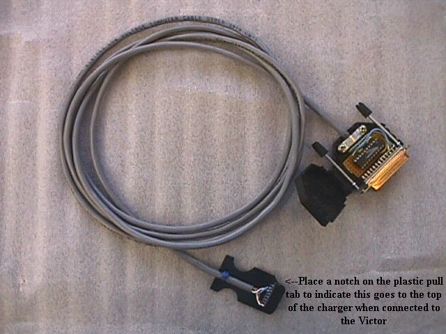
The information on this page is for an Interface Cable to be used with a serial printer or a PC running some type of terminal program. The Baud Rate is selectable in the Victor software under : Special Functions - Utilities - Baud-RT-Select = 5. Select the Baud-Rate that suites your Printer / PC.
I Assume NO RESPONSIBILITY ! for the construction of this Interface Cable by You or Someone else!
If you do not understand this information find somebody that does, or some serious damage can occur. Please check all your wiring many times before powering up. The interface chip can be housed in the DB-25 connector, providing that the outside case is plastic and not the metalized type (silver case) as this is conductive material and will cause an electrical short and fry the Maxim chip and maybe the Victor's CPU chip. You can build this on a small piece of Vero board from Radio Shack. You will need a 14 pin Ribbon Cable Header Connector (.100 inch Pin spacing) to plug into the Expansion Slot on the back of the Victor Charger and a 20 pin IC socket for the Maxim chip, and some 4 conductor wire. Remove the ribbon cable clamp you will not need this. On this connector you will solder 4 wires, be careful not to use to much solder or it will wick down the pins of the header connector and you will not be able to get it on the expansion slot pins of the Victor charger. Connect - One for +5 volts, One for Ground, One for Serial Out and One for Serial In. The output of the Chip you will solder to the DB-25 connector. See the diagram and picture below. CA glue a piece of plastic to the side of the the 14 pin header connector to make it easier to grab on to. When you are finished building the interface connect it to your charger without the Maxim chip installed. Power up the unit, check for +5 volts at the respective pins of the Maxim chip. Then shut off the Victor and install the Maxim chip in the IC socket. Cover the Maxim chip and IC socket with electrical tape, close up the DB-25 connector and power up your Victor with the Printer / PC connected and test.. Please study this carefully before attempting to build this..
I Assume NO RESPONSIBILITY ! for the construction of this Interface Cable by You or Someone else!
Schematic Diagram

Back of Victor

Completed Printer Cable

The Printer Cable Connected to the Victor Charger

